Budget
The budget is based off purchased parts, not tools or spare parts that was on hand.
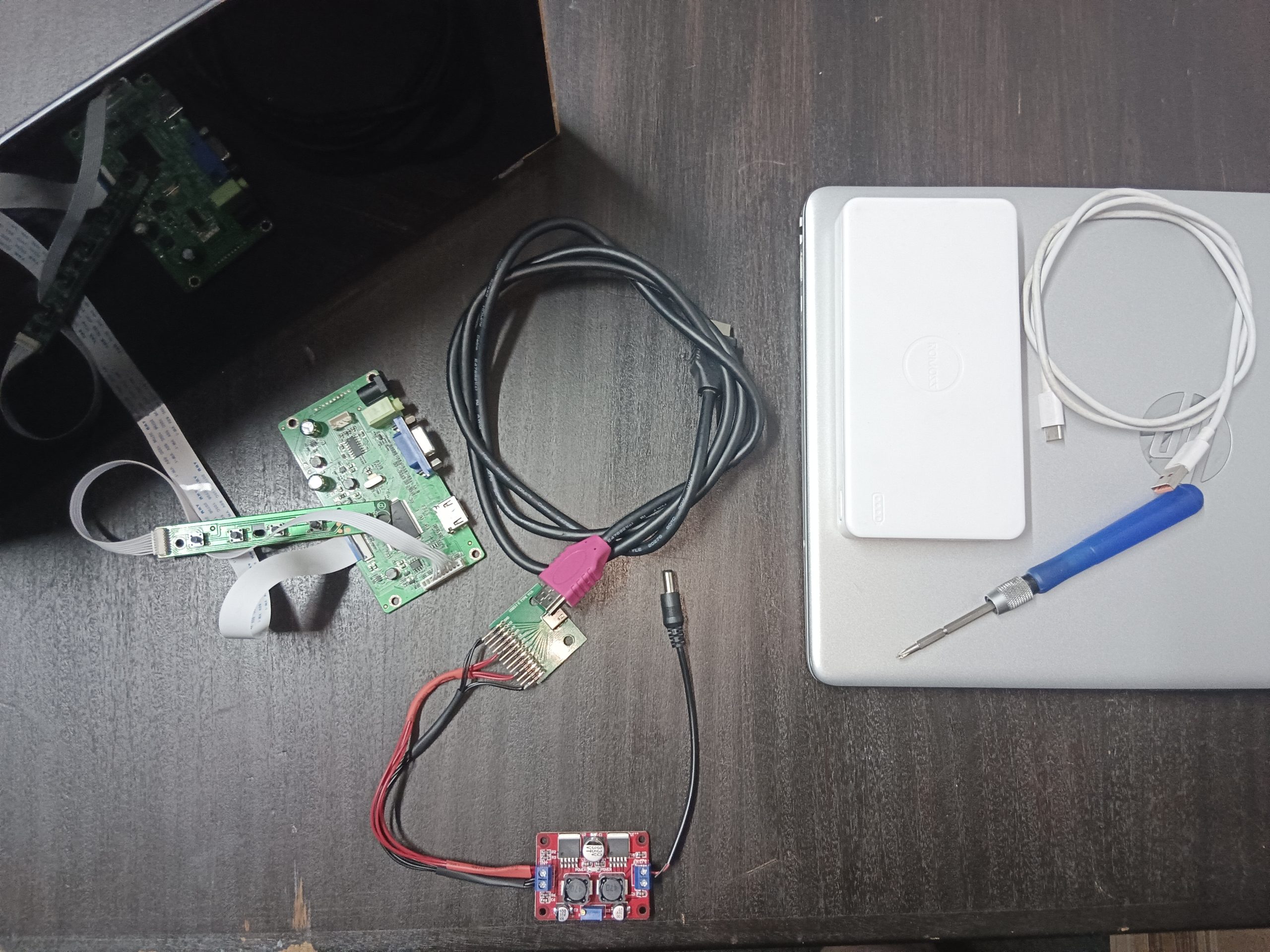
Est. Project Budget
R600 ~ R800
- LCD Screen Adapter - R400
- Buck-Boost Converter - R167
- USB-C Breakout Board - R34
- Tinned Hobby Wire - R61 (optional)
- Heat Shrink Tubes - R86 (optional)
- Male Power Adapter - R11
What will we be building?
Welcome to our exciting DIY project – crafting your very own portable USB-powered screen! Say goodbye to wasted old laptop parts and hello to innovation and convenience.
We’ve all experienced the frustration of load shedding, especially those of us in the IT world. Like many, I rely on multiple screens for productivity, and the recent Stage 4+ outages have been crippling. Plus, the sky-high prices of portable screens only add insult to injury.
But fear not! I embarked on a mission to find a solution that’s both portable and affordable. The answer? Harnessing the power of USB (v5) to create a versatile and easily detachable second screen.
Through thorough research and experimentation, I discovered that building a USB-powered screen is surprisingly straightforward. With a simple USB connection, you can power your screen from a charger block, laptop, or even a power bank – ensuring uninterrupted productivity wherever you go.
So join me on this journey as we unlock the potential of old laptop parts and embrace the freedom of portable screens. Let’s turn inconvenience into opportunity and revolutionize the way we work and play – one USB connection at a time!
What you will need
On Hand
- Spare Laptop Screen
- USB C Cable
- Power Bank
- USB Power Adapter (Phone Charger Block)
- HDMI Cable
- Lighter
Tools
- Insolation Tape
- Scissors
- Soldering Iron
- Solder
- Flat & Star Screwdrivers
- Wire
- Multimeter
Optionals
- Cable Cutters (Strippers)
Purchases
- LCD Screen Adapter
- Buck-Boost Converter
- USB-C Breakout Board
- Tinned Hobby Wire
- Heat Shrink Tubes
- Male Power Adapter
Where to buy
Please inform us if the links no longer work
Let's get building
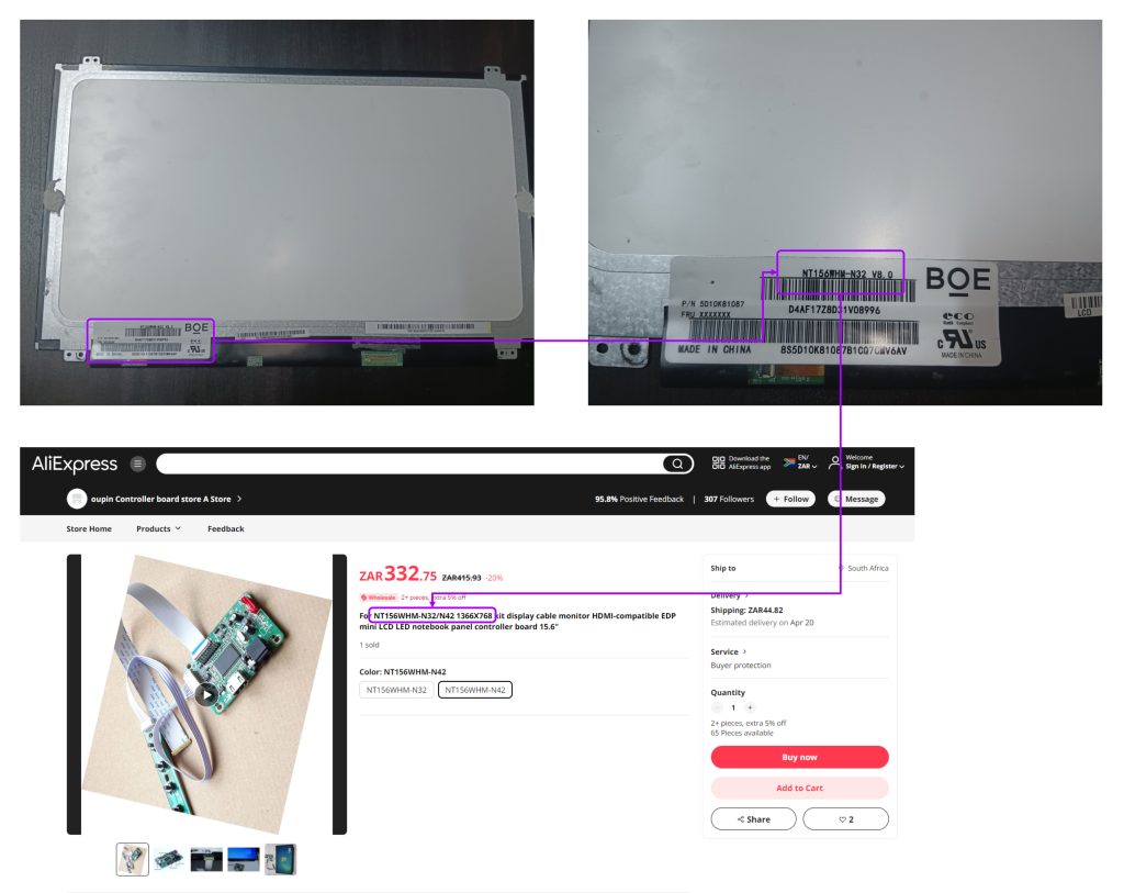
The very first thing to order (which may take up to 3 months to arrive thanks to the slow Import of South Africa) will be the adapter.
Turn your screen around and look at the serial, there should be one starting with NT or something similar.
Head to aliexpress.com and type in the serial with display controller. Eg: NT156WhM-N32 Display Controller.
This was roughly R400 with import costs, if there is an option to use Buffalo Logistics – I highly recommend them. They handle your import tax, and use FastWays or any local courier to have it delivered to your house. Turn around is about a month at the most.
As a hobbyist I have several items already on hand, where-as you may not. I have linked all the items to a refutable service where you can purchase them.
This is where you can either use wire you have on hand, and insolation tape instead if you do not want to buy the heat shrinks and tinned wire.
The main items that will be needed are [prices rounded up]:
- Buck-Boost Converter x1 (botshop.co.za) - R167
- USB-C Breakout Board x1 (communica.co.za) - R34
- Tinned Hobby Wire x100 (botshop.co.za) - R61 (optional)
- Heat Shrink Tubes x328 (botshop.co.za) - R86 (optional)
- Male Power Adapter x1 (botshop.co.za) - R11
The purchases have bulk tinned wire, and heat shrink tubes. I would recommend shopping around if you do not require such a large amount, and only need the handful for this project. Communica is the best place to check.
Once you have all the items and the import. There will be a few things needed to be able to test your DIY project.
- HDMI Cable
- Power Bank
- Phone Charger Block
- Laptop or PC
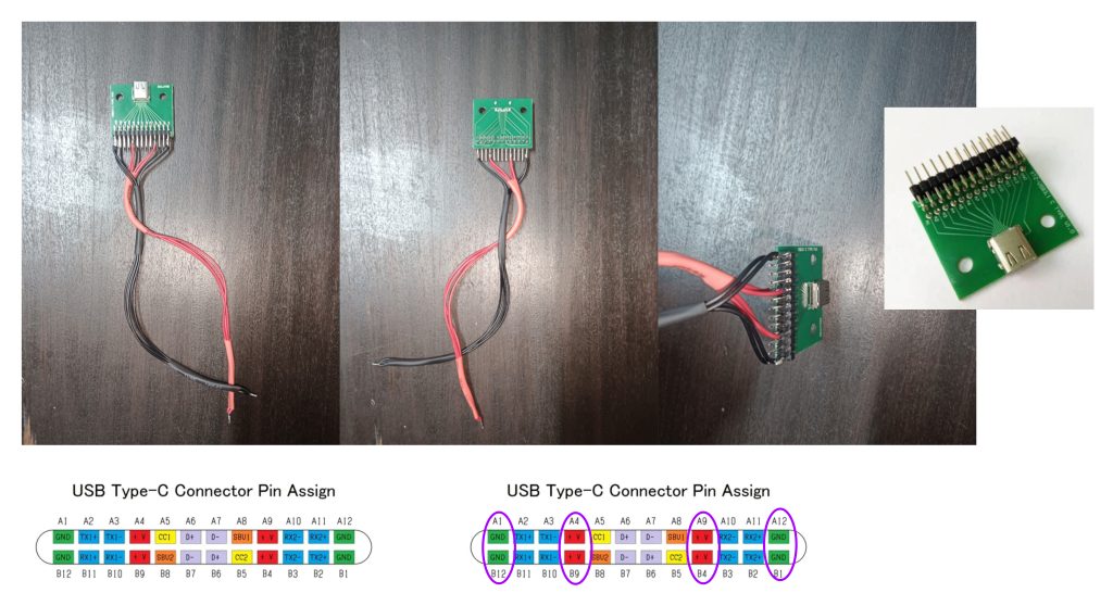
You will need:
- USB-C Breakout Board
- 4 Black tinned hobby wires (jumper wire)
- 4 Red tinned hobby wires (jumper wire)
- Solder
- Soldering Iron
- Heatshrink Tubes or Insulation Tape
Let’s get the daunting part out the way first. If you purchased the same board from Communica, you will see it has very specific labels under the breakout adapter (protruding pins).
Take note of the A1, B12, A12, B1 pins – these are Ground. This will serve as your Negative. Then, A4, B9, A9, B4pins – these are Power Sources. This will serve as your Positive.
Solder the corresponding tin wire’s to the breakout pins according to the diagram above.
Green = Negative
Red = Positive
In the photo’s provided you will see I have used heat shrink tube to keep the wires compact. You can use insolation tape here.
* Solder the tips together to make it easier when connecting it to the Buck-Boost Converter.
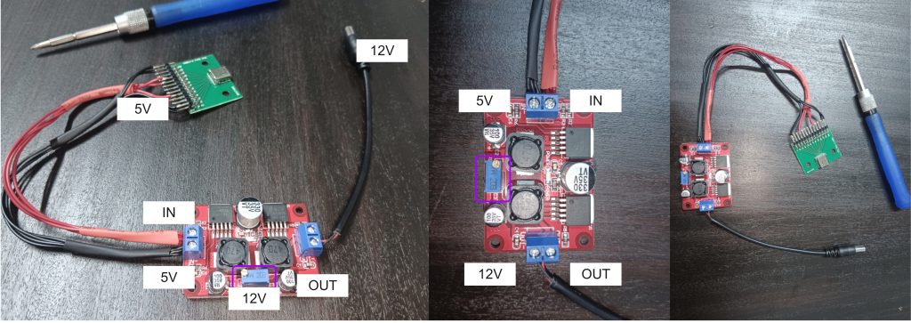
You will need:
- Screw Drivers (Flat and Star)
- Buck-Boost Converter
- Male Power Adapter
- Red and Black tinned hobby wire (jumper wire)
- Multi-Meter
Connect the Positive cable from the your Breakout Board to the + terminal on the In side of the board (see diagram above), do the same with the Negative cable to the – of the In terminal.
The breakout board will be providing 5v from your usb connection to the booster. This will then be converted into 12v which is needed to power the LCD Display Controller.
My diagram will be slightly different to the instructions that are to follow, I had a Male Adapter with a cable already, so I opted to use that. Attach the Positive and Negative tinned wire tot he terminal of your Male Adapter, then on the Out side of the booster, attach the cables accordingly to the + and –. Should then look like the second image above.
Once that is done, take you multi-meter and set it to AC Voltage. [The AC voltage symbol will be a “V” with a “∿” over the V].
Setting the multi-meter pins on the Out terminal screws you should get a reading. Using a flat screwdriver turn the blue terminal adjuster (see image 2), until you multi-meter shows 12.
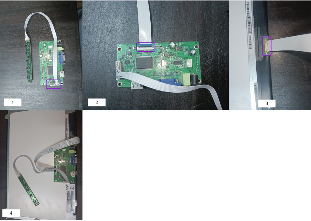
You will need:
- Spare Laptop Screen
- LCD Display Controller
Connect the control module to the board [1], then slide in the LCD ribbon cable [2], make sure the blue strip is at the top!. Attach the end of the ribbon cable to the back of your screen, it should slide in, be gentle here! [3]
[4] Complete assembly.
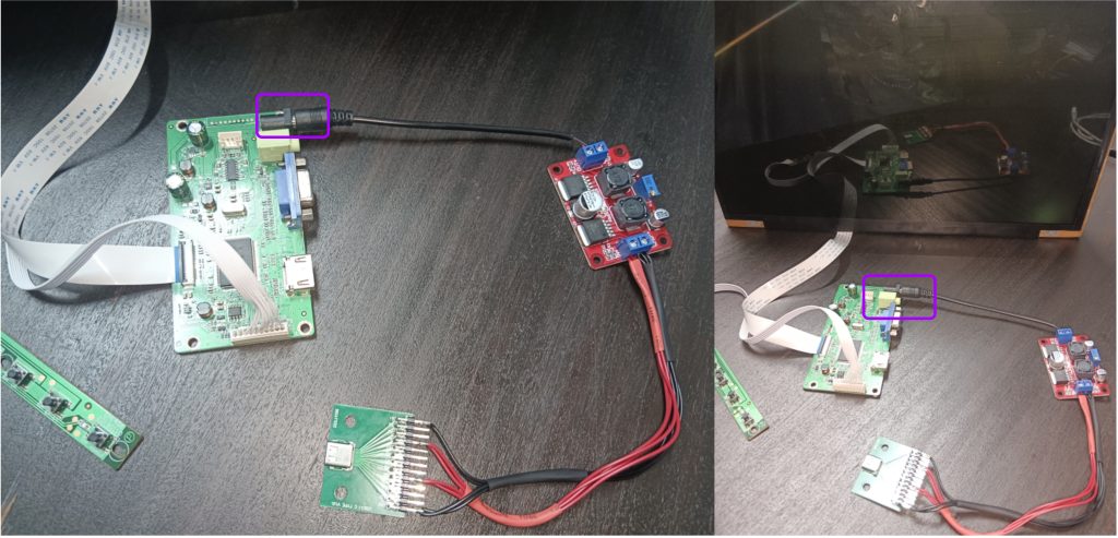
You will need:
- Screen Assembly
- Your Booster Assembly
Connect the Male Power Adapter to the power terminal of the LCD Display Controller
Finally now we can see if your house will blow up. Just kidding the voltage is too low :).
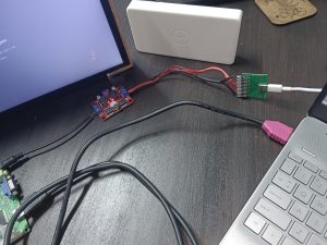
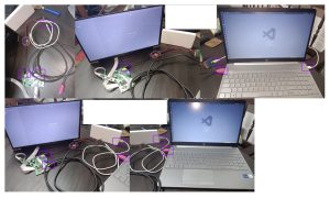
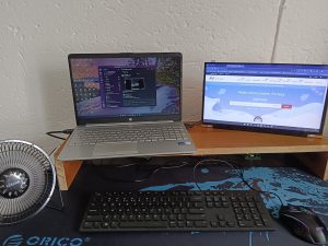
Connect your booster assembly to a powerbank, your laptop or the phone charger via the USB-C Breakout board. The screen should turn on and the Buck-Booster should show a red light. If the screen does not power on, on the control module look for the power button.
Connect the HDMI cable to the output of the LCD Display Controller, then plug it into your laptop.
You may want to adjust the Display settings to extend your screen if you are not wanting to make use of the Duplicate options.
Display options can be found in Settings or right click on your desktop and select Display Settings (Windows 11 - more options and then Display Settings)


Add comment